×
- Hello
- Login or Register
- Quick Links
- Live Chat
- Track Order
- Parts Availability
- RMA
- Help Center
- Contact Us
- Shop for
- Mazda Parts
My Garage
My Account
Cart
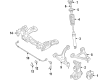
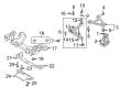
Genuine Mazda MX-5 Miata Control Arm
Suspension Arm- Select Vehicle by Model
- Select Vehicle by VIN
Select Vehicle by Model
orMake
Model
Year
Select Vehicle by VIN
For the most accurate results, select vehicle by your VIN (Vehicle Identification Number).
8 Control Arms found


Mazda MX-5 Miata Upper Control Arm Part Number: N243-34-200
$367.79 MSRP: $490.48You Save: $122.69 (26%)Ships in 1-2 Business Days


Mazda MX-5 Miata Lower Control Arm Part Number: N243-34-300C
$372.19 MSRP: $500.35You Save: $128.16 (26%)Ships in 1-2 Business Days


Mazda MX-5 Miata Lower Control Arm Part Number: NE51-34-350D
$316.95 MSRP: $422.68You Save: $105.73 (26%)Ships in 1-2 Business Days

Mazda MX-5 Miata Lower Control Arm Part Number: N243-34-350C
$372.19 MSRP: $500.35You Save: $128.16 (26%)Ships in 1-2 Business Days

Mazda MX-5 Miata Upper Control Arm Part Number: NH42-34-250
$248.40 MSRP: $331.27You Save: $82.87 (26%)Ships in 1-2 Business Days

Mazda MX-5 Miata Upper Control Arm Part Number: NH42-34-200
$274.68 MSRP: $366.30You Save: $91.62 (26%)Ships in 1-2 Business Days

Mazda MX-5 Miata Lower Control Arm Part Number: NE51-34-300D
$316.95 MSRP: $422.68You Save: $105.73 (26%)Ships in 1-2 Business Days

Mazda MX-5 Miata Upper Control Arm Part Number: N243-34-250
$367.79 MSRP: $490.48You Save: $122.69 (26%)Ships in 1-2 Business Days
Mazda MX-5 Miata Control Arm
Looking for Control Arm with proven quality? Choose OEM Control Arm. Mazda designs and builds them to strict factory specs. Every piece goes through rigorous quality checks. You'll get parts that fit right and work like new. Shop our huge inventory of OEM Mazda MX-5 Miata parts. Enjoy the highly competitive prices online. Our site is your one-stop shop. Each genuine MX-5 Miata part includes a manufacturer's warranty. Buy with confidence. Our return policy is simple and hassle-free. In a rush? Choose expedited delivery at checkout. You'll love the streamlined experience from search to checkout to receiving your order.
Mazda MX-5 Miata Control Arm Parts and Q&A
- Q: How to replace the front and lower control arms on Mazda MX-5 Miata?A:In the case of 2005 and older year models, start by loosening the front wheel lug nuts, lifting the vehicle up on jackstands and removing the front wheel. In case the wheel speed sensor harness is fitted with ABS, loosen the retaining band. Take out the shock absorber lower mounting bolt with the support of the lower control arm then remove the under cover on the front. Then unscrew the cotter pin and nut of upper balljoint, a small puller is used to loosen it up out of the upper control arm. The nut on the pivot bolt can be loosened with the wrench gripping the bolt head and the upper control arm may then be removed. Check the front and rear bushings of the lower control arm and replace those which are torn or cracked. Inspect the dust boot of a balljoint, tap it off if necessary, and stuff a new dust boot with grease then press it onto the balljoint stud making sure that there is a slight gap left. The reverse order of removal is followed during installation in that balljoint nut is tightened and a new cotter pin installed, the outer end of the lower control arm is raised to approximate normal ride height, and other fasteners tightened. Lastly, test and readjust the wheel alignment (where necessary). In the case of lower control arm, repeat the first steps of loosening lug nuts, putting the vehicle on the hoist, and taking off the wheel, in the front. Disconnect the stabilizer bar link bolt and take off the shock absorber lower bolt. Take out the balljoint through-bolt and the top bolt that holds the balljoint to the lower control arm and then remove the inner pivot bolts that hold the lower control arm to the frame, but first note the location of the adjusting cams. Bring the inner end of the arm downwards, and take it out of under the vehicle. Check the bushings and reverse the installation process, tightening the balljoint bolts as it is raised in the air and the vehicle is simulating the normal ride height before loose fitting other fasteners are tightened. In the case of 2006 and above models, begin by loosening the wheel lug nuts, lifting the vehicle and removing the front wheels. Disconnect the ABS wheel speed sensor of the Steering Knuckle and place it aside, in a safe manner. Unbolt the brake hose bracket of the upper control arm, and unbolt the upper control arm balljoint of the steering knuckle, making sure the brake hose is first disconnected. Take out the upper control arm pivot bolts, nuts, unattach the shock absorber, and then take out the upper control arm and shock absorber. A reverse operation of removal is installation, where all the fasteners are tightened to the required torque. In the case of the lower control arm, loosen the front brake caliper mounting bracket by unbolstering it and remove the caliper and bracket as a unit. Loose the lower control arm rear pivot bolt, remove the steering knuckle and make a mark indicating where the caster adjusting cam is. Identify the cam position marking camber and then remove lower control arm front pivot bolt and remove lower control arm. Installation is once again the opposite of removal, clamping all the fasteners to the required torque and simulating normal ride height after which any fastener that passes through a rubber bushing should be tightened, then checking and adjusting the wheel alignment as needed.
- Q: How to remove and install the lower and upper control arms on Mazda MX-5 Miata?A:This is only applicable to 2005 and earlier models. In the process of removing the lower control arm, one should first of all, loosen the rear wheel lug nuts, raise the rear of the car and then firmly hold it on jackstands and then remove the wheel. Prop up the lower arm using a floor jack and then unbolt the lower end of the shock absorber/ coil spring assembly and the stabilizing bar tie on the control arm. Clean up the surrounding of the wheel adjusting the inner pivot points of the control arm, mark the location of the cam plate on the individual pivot bolts of control arm lower and the location of adjusting cams to be reinstated. Unscrew the outer pivot bolt of the control arm, then the pivot bolts that are on the inside, and then disconnect the control arm of the car. The bushings of the inner and the outer ends of the control arms are pressable in and out. Installation begins with installing the inner pivot bolt of the control arm, and connecting the cam plates to the allocated positions. Install the inner and outer pivot bolts next without tightening them completely and lastly the stabilizer bar link bolt and lower shock absorber bolt. Lift the rear knuckle using a floor jack to create a simulated normal ride height, and then attach the suspension fasteners to required torques. Install the lug nuts and the wheel, lower the vehicle and fix the lug nuts of the wheel to the torque. Lastly, check and adjust the rear wheel alignment of the car. In case of the upper control arm, loosen the wheel lug nuts, lift the vehicle, and hold it properly placed on jackstands and then remove the wheel. Lift-up the lower control arm using a floor jack, and pivot-bolts at the outer end of an upper control arm and the two inner end points will then be removed to release the rear upper control arm. Install control arm inner and outer pivot bolts, position the lower control arm elevated like normal ride height using a floor jack, tighten the bolts to recommended torque values. Install lug nuts, wheel, and lower the vehicle then tighten the lug nuts to the torque after which the rear wheel alignment should be checked and adjusted.


Related Mazda MX-5 Miata Parts
 Mazda MX-5 Miata Axle Pivot Bushing
 Mazda MX-5 Miata Axle Support Bushings
 Mazda MX-5 Miata Bump Stop
 Mazda MX-5 Miata Camber and Alignment Kit
 Mazda MX-5 Miata Coil Spring Insulator
 Mazda MX-5 Miata Control Arm Bolt
 Mazda MX-5 Miata Front Cross-Member
 Mazda MX-5 Miata Steering Knuckle
 Mazda MX-5 Miata Strut Housing
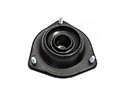 Mazda MX-5 Miata Strut Mounts
 Mazda MX-5 Miata Sway Bar Link Bushing
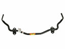 Mazda MX-5 Miata Sway Bars
Browse by Year
2025 Control Arm 2024 Control Arm
2023 Control Arm
2022 Control Arm
2021 Control Arm
2020 Control Arm
2019 Control Arm
2018 Control Arm
2017 Control Arm
2016 Control Arm
2015 Control Arm
2014 Control Arm
2013 Control Arm
2012 Control Arm
2011 Control Arm
2010 Control Arm
2009 Control Arm
2008 Control Arm
2007 Control Arm
2006 Control Arm