×
- Hello
- Login or Register
- Quick Links
- Live Chat
- Track Order
- Parts Availability
- RMA
- Help Center
- Contact Us
- Shop for
- Mazda Parts
My Garage
My Account
Cart
Genuine Mazda RX-7 Control Arm
Suspension Arm- Select Vehicle by Model
- Select Vehicle by VIN
Select Vehicle by Model
orMake
Model
Year
Select Vehicle by VIN
For the most accurate results, select vehicle by your VIN (Vehicle Identification Number).
10 Control Arms found

Mazda RX-7 Lower Control Arm Part Number: FC02-34-300
$677.43 MSRP: $925.64You Save: $248.21 (27%)Ships in 1-2 Business Days

Mazda RX-7 Upper Control Arm Part Number: F131-34-250
$394.53 MSRP: $530.39You Save: $135.86 (26%)Ships in 1-2 Business Days
Mazda RX-7 Lower Control Arm Part Number: FD01-28-300B
$819.36 MSRP: $1119.57You Save: $300.21 (27%)Ships in 1-2 Business DaysMazda RX-7 Upper Control Arm Part Number: FD01-28-2A0B
$693.08 MSRP: $947.02You Save: $253.94 (27%)Ships in 1-2 Business DaysMazda RX-7 Lower Control Arm Part Number: F131-34-300B
$776.86 MSRP: $1061.50You Save: $284.64 (27%)Ships in 1-2 Business Days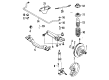
Mazda RX-7 Control Arm Part Number: FA54-49-310
$224.34 MSRP: $299.17You Save: $74.83 (26%)Ships in 1-2 Business DaysMazda RX-7 Lower Control Arm Part Number: FC02-34-350
Mazda RX-7 Control Arm Part Number: FA54-49-320
Mazda RX-7 Lower Control Arm Part Number: F131-34-350B
Mazda RX-7 Upper Control Arm Part Number: F131-34-200
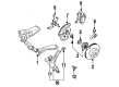
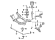
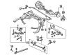
Mazda RX-7 Control Arm
Looking for Control Arm with proven quality? Choose OEM Control Arm. Mazda designs and builds them to strict factory specs. Every piece goes through rigorous quality checks. You'll get parts that fit right and work like new. Shop our huge inventory of OEM Mazda RX-7 parts. Enjoy the highly competitive prices online. Our site is your one-stop shop. Each genuine RX-7 part includes a manufacturer's warranty. Buy with confidence. Our return policy is simple and hassle-free. In a rush? Choose expedited delivery at checkout. You'll love the streamlined experience from search to checkout to receiving your order.
Mazda RX-7 Control Arm Parts and Q&A
- Q: How to properly replace the control arm and knuckle arm on Mazda RX-7?A:Raise the front side of the vehicle and hold it steadily by use of stands then remove the front wheel. Then screw the two knuckle arm holding bolts on the lower end of the Shock Absorber and have access by sliding the steering wheel laterally, and record the length and location of the bolts. Detach the tie-rod end with an appropriate puller, or otherwise a typical gear puller, by first unscrewing the cotter pin and loosening the lock nut, and then with by pushing the end of the rubber bushing downward to position the puller and push the joint out. Disassemble the tension rod the suspension arm by unscrewing the attaching nuts on the lower side and the stabilizer bar to the suspension arm by removing the control link, with lock nut and jamb nut on the top. Unattach the suspension arm with the bolt on the inboard end with two wrenches then unattach the suspension arm with the knuckle arm. Use a puller to separate the knuckle arm and the suspension arm by keeping note of how the two relate to each other to be put back together and check them out to be damaged or deformed including checking the balljoint and dust cover as well as the arm bushing. As required, change parts, paying attention to the fact that the suspension arm and balljoint may be a unit which should be replaced together in case of defects. The bushing in the suspension arm can be easily pressed out and it can be replaced with ease by using a socket and no lubricant is required. Install the knuckle arm to the suspension arm so that the threaded stop bolt is facing the front and then tighten the lock nut to about 46 ft-lb and install the cotter pin. Bend back the cotter pin across the nut, and cut off where necessary, and then fit in place the suspension arm, and attaching bolt and nut but not tightened. Installation: Move and then loosely screw on the two balljoint-to-knuckle arm bolts (making sure that the short one is in front and the longer in the back), ensuring that you move the steering out of the way. Install the two attaching bolts using the tension rod and torque to 40-50 ft-lb, install the control link using the suspension arm and attach the stabilizer bar by tightening the lock nut and installing the jam nut. Install the tie-rod on the knuckle arm and screw the locking nut to an approximate of 22 ft-lb and lock the cotter pin. Completely screw the two already installed knuckle arm bolts to a torque of 43 to 68 ft-lb then fit the wheel and bring the vehicle to the ground. Bounce the car at a few times until the suspension is at rest, and then tighten the arm of the suspension attaching the bolt to 29 to 40 ft-lb. Lastly, place the engine under cover pan and also road test the vehicle and also ensure that there is no noise or excessive movement and it is also advisable to align the front of the vehicle as it may have slightly changed.
Related Mazda RX-7 Parts
 Mazda RX-7 Axle Beam Mount
 Mazda RX-7 Axle Shaft
 Mazda RX-7 Axle Support Bushings
 Mazda RX-7 Ball Joint
 Mazda RX-7 Coil Spring Insulator
 Mazda RX-7 Control Arm Bushing
 Mazda RX-7 Front Cross-Member
 Mazda RX-7 Steering Knuckle
 Mazda RX-7 Strut Housing
 Mazda RX-7 Sway Bar Bracket
 Mazda RX-7 Trailing Arm
 Mazda RX-7 Wheel Bearing
Browse by Year
1995 Control Arm
1994 Control Arm
1993 Control Arm
1991 Control Arm
1990 Control Arm
1989 Control Arm
1985 Control Arm
1984 Control Arm