×
- Hello
- Login or Register
- Quick Links
- Live Chat
- Track Order
- Parts Availability
- RMA
- Help Center
- Contact Us
- Shop for
- Mazda Parts
My Garage
My Account
Cart
Genuine 1991 Mazda B2200 Rack and Pinions
Steering Rack- Select Vehicle by Model
- Select Vehicle by VIN
Select Vehicle by Model
orMake
Model
Year
Select Vehicle by VIN
For the most accurate results, select vehicle by your VIN (Vehicle Identification Number).
1 Rack and Pinions found

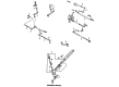
1991 Mazda B2200 Pinion Part Number: UB39-32-130
$391.64 MSRP: $526.51You Save: $134.87 (26%)Ships in 1-2 Business DaysProduct Specifications- Other Name: Screw Gear; Worm Shaft
- Item Weight: 5.10 Pounds
- Condition: New
- Fitment Type: Direct Replacement
- SKU: UB39-32-130
- Warranty: This genuine part is guaranteed by Mazda's factory warranty.
1991 Mazda B2200 Rack and Pinions Parts and Q&A
- Q: How to remove and install the rack and pinions assembly from a 2WD or 4WD on 1991 Mazda B2200?A: To extract the rack and pinion assembly in a 2WD MPV, it is either lift the vehicle and then take off the wheel and tire assembly in addition to the splash shield and then position the front wheels in a straight line. Then remove the cotter pins and nutts of both tie rod end studs, with a separator tool to remove tie rod ends of the knuckles. De-pinch bolt in the intermediate shaft-to-pinion shaft connection, de-connect and plug the pressure line in the rack and pinion kit and loosen the clamp to de-connect the return line and plug it. In case of an automatic transmission of the vehicle, then dismantle the change counter assembly so that the protector plate mounting bolt can be reached. It is then necessary to remove the steering bracket mounting bolts and the rack and pinion assembly with the brackets, removing the brackets where required. To install, in case brackets were taken off, replace them and clamp mounting bolts to 54-69 ft. lbs. (74-93Nm). Install pinion and rack assembly and brackets and assemble the bracket-to-chassis bolts to 46-69 ft. lbs. (63-93Nm). Install the change counter assembly, as necessary, hook the return line up, and screw the clamp together and then hook the pressure line and screw the nut to 23-35 ft. lbs. (31-47Nm). Install pinch bolt in the intermediate shaft-to-pinion shaft coupling and tighten with a range of 13-20 ft. lbs. (18-26Nm). Install the tie rod end studs in the knuckles, the nuts, tighten them 43-58 ft. lbs. (59-78Nm) and replace the cotter pin. Lastly, reattach splash shield and wheel and tire assembly, lower car and bleed power steering. In the case of a 4WD MPV, initial steps to be taken are the removal of the wheel and tire assemblies and splash shield and then the tie rod ends are removed with the help of the separator tool. Loose the pressure and return hoses, de-load the lines of the pinch bolt, rack and pinion assembly, and the pinch bolt. Open the car and take out the lower panel and column cover and unbolt the steering column and push it back as far as possible to decouple the intermediate shaft and the pinion shaft. Mark the front drive shaft location on the axle flange, remove the same and remove the rack and pinion assembly mounting bracket bolts and front differential/joint shaft assembly mounting bolts. Move the differential/joint shaft assembly back, then move and flip the rack and pinion assembly 90 degrees, and then remove it on the left hand of the car. Installation To install, put the rack and pinion assembly in the right side, rotate it 90 degrees, and slide it all forward until the mounting bolts are in place with a tightening of 54-69 ft. lbs. (74-93Nm) to 90. Install the differential/joint shaft assembly and screw the mounting bolts into the shaft to 49-72 ft. lbs. (67-97Nm) and reinstall the driveshaft to line up with the marks that were made during removal. Install the intermediate shaft by connecting it with the pinion shaft, screwing the steering column nuts and bolts to 12-17 ft. lbs. (16-23Nm), and reconnect the lower panel and column cover. Install pinch bolt in the intermediate shaft-to-pinion shaft coupling and tighten with a range of 13-20 ft. lbs. (18-26Nm). Reconnect the pressure and return lines to the rack and pinion assembly, lay the hoses in place, fit the tie rod end studs in the knuckles, fit the nuts, tighten them to 43-58 ft. lbs. (59-78Nm) and replace cloth cotter pins. Lastly, reattach splash shield and wheel and tire assembly, lower car and bleed power steering.
Related 1991 Mazda B2200 Parts
 1991 Mazda B2200 Alternator
 1991 Mazda B2200 Clutch Master Cylinder
 1991 Mazda B2200 Crankshaft Timing Gear
 1991 Mazda B2200 Harmonic Balancer
 1991 Mazda B2200 Instrument Cluster
 1991 Mazda B2200 Power Steering Hose
 1991 Mazda B2200 Spark Plug Wire