×
- Hello
- Login or Register
- Quick Links
- Live Chat
- Track Order
- Parts Availability
- RMA
- Help Center
- Contact Us
- Shop for
- Mazda Parts
My Garage
My Account
Cart
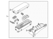
Genuine Mazda Tribute Relay Boxes
Relay Block- Select Vehicle by Model
- Select Vehicle by VIN
Select Vehicle by Model
orMake
Model
Year
Select Vehicle by VIN
For the most accurate results, select vehicle by your VIN (Vehicle Identification Number).
12 Relay Boxes found

Mazda Tribute Fuse & Relay Box Part Number: ZZC4-67-010
$440.55 MSRP: $592.26You Save: $151.71 (26%)Ships in 1-2 Business DaysMazda Tribute Fuse & Relay Box Part Number: ZZC8-67-010
$485.82 MSRP: $653.12You Save: $167.30 (26%)Mazda Tribute Fuse & Relay Box Part Number: ZZC9-67-010
$335.19 MSRP: $439.97You Save: $104.78 (24%)Ships in 1-2 Business Days

Mazda Tribute Fuse & Relay Box Part Number: ZZDB-67-010
$686.16 MSRP: $937.57You Save: $251.41 (27%)Mazda Tribute Fuse & Relay Box Part Number: ZZEB-67-010
$125.46 MSRP: $164.68You Save: $39.22 (24%)Ships in 1-2 Business DaysMazda Tribute Fuse & Relay Box Part Number: ZZED-67-010
$304.89 MSRP: $400.20You Save: $95.31 (24%)Ships in 1-2 Business DaysMazda Tribute Fuse & Relay Box Part Number: ZZC5-67-010
Mazda Tribute Fuse & Relay Box Part Number: ZZC7-67-010
Mazda Tribute Fuse & Relay Box Part Number: ZZCA-67-010A
Mazda Tribute Fuse & Relay Box Part Number: ZZEA-67-010
Mazda Tribute Fuse & Relay Box Part Number: ZZEE-67-010
Mazda Tribute Fuse & Relay Box Part Number: ZZEG-67-010
Mazda Tribute Relay Boxes
Looking for Relay Boxes with proven quality? Choose OEM Relay Boxes. Mazda designs and builds them to strict factory specs. Every piece goes through rigorous quality checks. You'll get parts that fit right and work like new. Shop our huge inventory of OEM Mazda Tribute parts. Enjoy the highly competitive prices online. Our site is your one-stop shop. Each genuine Tribute part includes a manufacturer's warranty. Buy with confidence. Our return policy is simple and hassle-free. In a rush? Choose expedited delivery at checkout. You'll love the streamlined experience from search to checkout to receiving your order.
Mazda Tribute Relay Boxes Parts and Q&A
- Q: What are the functions and testing procedures for Relay Boxes in vehicle electrical systems on Mazda Tribute?A:The vehicle has several electrical accessories like the fuel injection system, horns, starter and fog lamps that make use of relays to send electrical signals to the components. Relays are activated by a low current control circuit to switch a high current power current and a failed relay in a circuit means the failure to operate the component involved appropriately. The majority of the relays are inside the fusel relay box or SJB which is located in the engine compartment, and some special relays are in the interior fuse boxes or BCM/fuse box. When a defective relay is suspected, it may be pulled off and checked by a particular process or by any service department or repair shop of the dealer and faulty relays should be replaced as a unit. The most common types of relays are usually known as ISO relays and the terminals are numbered to represent the typical circuit connections and functions. Two terminals can be the relay control circuit, which is connected to the relay coil, and the other terminals belong to the power one. The coil, when excited, induces a magnetic field that closes the greater contacts of the power circuit, putting power into the circuit loads. Terminal 85 and 86 are a typical setup of a control circuit where terminal 86 is connected to battery positive voltage and terminal 85 to ground in case of a diode or in case of a resistor, the circuit can use either terminal 85 or 86. Terminal 30 is typically connected to the battery voltage source when circuit loads are required, whereas terminal 87 is connected to the powered component with other terminals labeled 87A, 87B, etc. being available as alternative load or ground connections. The continuity should be checked with the help of the ohmmeter using the relay control coil, and the meter must be connected with the lead as indicated in the polarity in one case and with the opposite lead in another. In the case of a resistor, the resistance in either direction should be the same and a diode will have increased resistance in the forward polarity direction. An infinite resistance in either direction is an indication of the replacement of a relay. Once the relay has been removed, continuity of the power circuit terminals should be tested and no continuity between terminal 30 and 87 when the relay is de-energized. Reducing a fused jumper wire to terminal 86 and positive battery terminal will accomplish this along with using another jumper between terminal 85 and ground to make the relay click. Through these links, there should now be continuity between terminals 30 and 87. In case the relay fails any of these tests, it was found that the relay should be replaced.

Related Mazda Tribute Parts
 Mazda Tribute Ignition Switch
 Mazda Tribute Air Intake Hose
 Mazda Tribute Belt Tensioner
 Mazda Tribute Fuel Pressure Regulator
 Mazda Tribute Fuel Tank Filler Neck
 Mazda Tribute Fuel Tank Strap
 Mazda Tribute Oil Filler Cap
 Mazda Tribute Wiper Blade
 Mazda Tribute Wiper Linkage