×
- Hello
- Login or Register
- Quick Links
- Live Chat
- Track Order
- Parts Availability
- RMA
- Help Center
- Contact Us
- Shop for
- Mazda Parts
My Garage
My Account
Cart
Genuine Mazda B2000 Steering Knuckle
Front Steering Knuckle- Select Vehicle by Model
- Select Vehicle by VIN
Select Vehicle by Model
orMake
Model
Year
Select Vehicle by VIN
For the most accurate results, select vehicle by your VIN (Vehicle Identification Number).
1 Steering Knuckle found

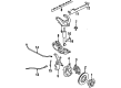
Mazda B2000 Knuckle Part Number: UB39-33-031B
$273.19 MSRP: $364.33You Save: $91.14 (26%)Ships in 1-2 Business Days
Mazda B2000 Steering Knuckle
Looking for Steering Knuckle with proven quality? Choose OEM Steering Knuckle. Mazda designs and builds them to strict factory specs. Every piece goes through rigorous quality checks. You'll get parts that fit right and work like new. Shop our huge inventory of OEM Mazda B2000 parts. Enjoy the highly competitive prices online. Our site is your one-stop shop. Each genuine B2000 part includes a manufacturer's warranty. Buy with confidence. Our return policy is simple and hassle-free. In a rush? Choose expedited delivery at checkout. You'll love the streamlined experience from search to checkout to receiving your order.
Mazda B2000 Steering Knuckle Parts and Q&A
- Q: How to remove and install the Steering Knuckle on Mazda B2000?A:To remove the components, first raise and support the front end on jacks or stands, then remove the wheels. Check the brake rotor for any noticeable bearing play; there should be none. If play is detected, proceed accordingly. Next, remove the caliper and suspend it out of the way, followed by the locking hub, snapring, spacer, set bolts, bearing set plate, and locknut. Carefully pull off the hub and plate, ensuring to catch the washer and bearing. Remove the caliper mounting plate and knuckle arm, disconnect the stabilizer bar, and remove the tie rod end nut, using a separator to disconnect the tie rod end. Unbolt the lower end of the shock absorber, then remove the snapring and spacer from the outer end of the Axle Shaft. Support the lower control arm with a floor jack, then remove the lower ball joint nut and disconnect the lower ball joint from the knuckle with a separator. Repeat this for the upper ball joint, then lower the jack and remove the knuckle. For disassembly, place the knuckle in a soft-jawed vise, pry out the oil seal, and drive out the outer bearing race using a hammer and brass drift. Use a slide hammer and adapter to remove the needle bearing from the knuckle, matchmark the brake rotor and hub, remove the bolts, and lift off the rotor. Remove the hub oil seal and bearing, then drive out the inner bearing race. During assembly, coat the outer surface of a new needle bearing assembly with wheel bearing grease and drive it into place. Drive a new inner bearing race into the knuckle, install a new inner bearing in the hub, and install a new oil seal, coating the seal lip with grease. Drive a new outer bearing race and inner bearing outer race into the hub, then drive a new oil seal into place until flush with the hub end surface, applying grease to the seal lip. Install the rotor, aligning the matchmarks, and torque the bolts to 50 ft. lbs. Pack the inside of the hub with grease and install the outer bearing race and washer. For installation, position the knuckle on the shaft and connect the ball joints, tightening the upper ball joint nut to 38 ft. lbs. and the lower to 116 ft. lbs. with new cotter pins. Install the spacer and snapring, connect the shock absorber with bolts torqued to 58 ft. lbs., and connect the stabilizer bar, tightening the nut so that the end of the bolts projects 14mm past the locknut. Install the rotor dust shield with bolts torqued to 10 ft. lbs., connect the tie rod end with the nut torqued to 43 ft. lbs. using a new cotter pin, and install the caliper support and knuckle arm. Install the hub and rotor assembly, tighten the locknut, and turn the hub 2 or 3 complete turns to seat the bearings. Loosen the locknut until it can be turned by hand, then attach a pull scale to a wheel lug to check the bearing rotational effort, which should be between 1.3-2.6 lb. If not, tighten the locknut until within specifications. Finally, install the set bolts, set plate, snapring, spacer, locking hub, caliper, and wheels.
Related Mazda B2000 Parts
 Mazda B2000 Axle Beam Mount
 Mazda B2000 Axle Shaft
 Mazda B2000 Axle Support Bushings
 Mazda B2000 Control Arm Bushing
 Mazda B2000 Shock Absorber
 Mazda B2000 Strut Housing
 Mazda B2000 Sway Bar Bracket
 Mazda B2000 Sway Bar Bushing
 Mazda B2000 Sway Bar Link Bushing
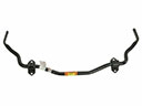 Mazda B2000 Sway Bars
 Mazda B2000 Wheel Bearing Dust Cap
 Mazda B2000 Wheel Seal