×
- Hello
- Login or Register
- Quick Links
- Live Chat
- Track Order
- Parts Availability
- RMA
- Help Center
- Contact Us
- Shop for
- Mazda Parts

My Garage
My Account
Cart
Genuine Mazda Torsion Bar
Suspension Torsion Bar- Select Vehicle by Model
- Select Vehicle by VIN
Select Vehicle by Model
orMake
Model
Year
Select Vehicle by VIN
For the most accurate results, select vehicle by your VIN (Vehicle Identification Number).
31 Torsion Bars found
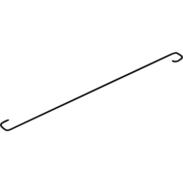
Mazda Torsion Bar Part Number: B25D-52-792C
$35.80 MSRP: $46.99You Save: $11.19 (24%)Ships in 1-2 Business DaysProduct Specifications- Other Name: Spring Left
- Position: Driver Side
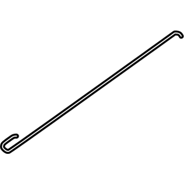
Mazda Torsion Bar Part Number: NC10-52-791B
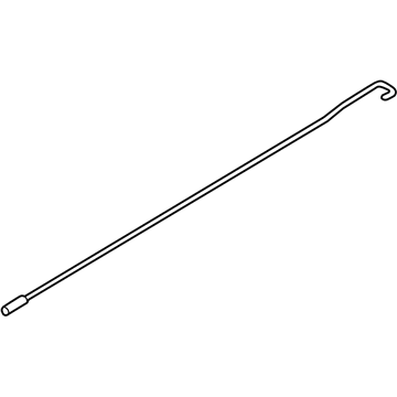
$20.04 MSRP: $49.24You Save: $29.20 (60%)Ships in 1-2 Business DaysProduct Specifications- Other Name: Spring(Right), Balance
- Position: Passenger Side
- Replaces: NC10-52-791A
Mazda Torsion Bar Part Number: GMD9-52-7A0A
$30.78 MSRP: $41.04You Save: $10.26 (25%)Ships in 1-2 Business DaysProduct Specifications- Other Name: Spring(Right), Balance
- Position: Passenger Side
- Replaces: GMD9-52-7A0
Mazda Torsion Bar Part Number: GMD9-52-7B0A
$31.69 MSRP: $42.26You Save: $10.57 (26%)Ships in 1-2 Business DaysProduct Specifications- Other Name: Spring(Left), Balance
- Position: Driver Side
- Replaces: GMD9-52-7B0
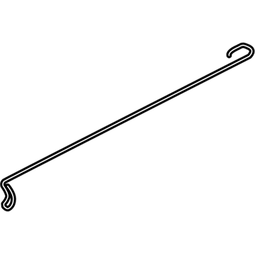
Mazda Torsion Bar Part Number: NC10-52-792B
$36.93 MSRP: $49.24You Save: $12.31 (25%)Ships in 1-2 Business DaysProduct Specifications- Other Name: Spring(Left), Balance
- Position: Driver Side
- Replaces: NC10-52-792A
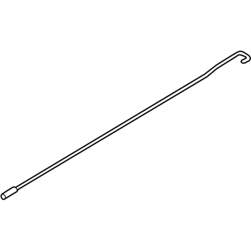
Mazda Torsion Bar Part Number: GBFN-52-7B0
$37.24 MSRP: $49.67You Save: $12.43 (26%)Ships in 1-2 Business DaysProduct Specifications- Other Name: Spring(Left), Balance
- Position: Driver Side
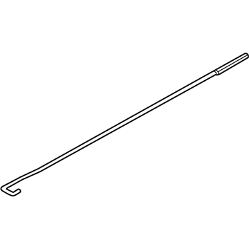
Mazda Torsion Bar Part Number: GBFN-52-7A0
$38.35 MSRP: $51.15You Save: $12.80 (26%)Ships in 1-2 Business DaysProduct Specifications- Other Name: Spring(Right), Balance
- Position: Passenger Side
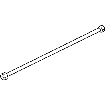
Mazda Torsion Bar Part Number: ZZP1-34-011
$69.41 MSRP: $91.10You Save: $21.69 (24%)Ships in 1-2 Business DaysProduct Specifications- Other Name: Spring Right, Torsion
Mazda Torsion Bar Part Number: ZZP0-34-021
$223.94 MSRP: $293.94You Save: $70.00 (24%)Ships in 1-2 Business DaysProduct Specifications- Other Name: Spring Left, Torsion
- Position: Driver Side

Mazda Torsion Bar Part Number: B01K-52-792A
$45.74 MSRP: $61.00You Save: $15.26 (26%)Ships in 1-2 Business DaysProduct Specifications- Other Name: Spring(Left), Balance
- Position: Driver Side
Mazda Torsion Bar Part Number: UB39-34-011
$218.75 MSRP: $291.72You Save: $72.97 (26%)Ships in 1-2 Business DaysProduct Specifications- Other Name: Torsion Spring (Right)
- Position: Passenger Side
Mazda Torsion Bar Part Number: ZZP2-34-021
Product Specifications- Other Name: Spring Left, Torsion
Mazda Torsion Bar Part Number: ZZP2-34-011
Product Specifications- Other Name: Spring Right, Torsion
Mazda Torsion Bar Part Number: ZZP1-34-021
Product Specifications- Other Name: Spring Left, Torsion
Mazda Torsion Bar Part Number: ZZP0-34-011
Product Specifications- Other Name: Spring Right, Torsion
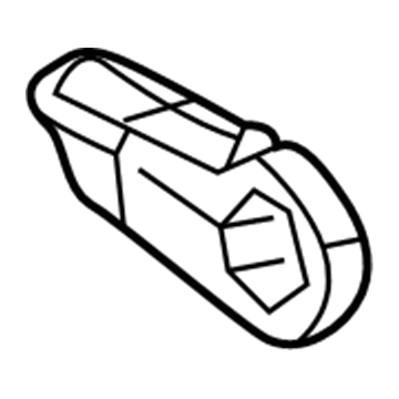
Mazda Torsion Bar Adjuster Part Number: ZZP0-34-008A
Product Specifications- Other Name: Arm, Adjust Lever; Adjust Arm
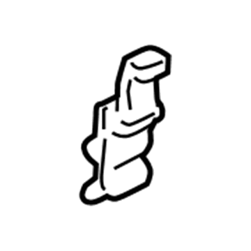
Mazda Torsion Bar Holder Part Number: NA01-56-805
Product Specifications- Other Name: Holder
Mazda Torsion Bar Part Number: N115-52-791A
Product Specifications- Other Name: Spring Right
- Position: Passenger Side
Mazda Torsion Bar Part Number: H26052791C
Product Specifications- Other Name: Spring Right
- Position: Passenger Side
Mazda Torsion Bar Part Number: GJ22-56-851A
Product Specifications- Other Name: Spring Right
- Position: Passenger Side
| Page 1 of 2 |Next >
1-20 of 31 Results
Mazda Torsion Bar
With its twisting motion, the Mazda Torsion Bar provides support while carrying the weight of the vehicle. It is designed to smooth out bumps in the road. Thus, every Mazda driver enjoys a level ride. Even in the worst the city has to offer, you are not jarred. Mazda takes great pride in having its vehicles combine energetic performance with efficiency. In this lightweight bodywork, SKYACTIV drivetrains and KODO lines look poised to pounce. With everything from small hatches to SUVs, Mazda gives you the same exact steering fun and i-ACTIVSENSE technology that helps families feel safe while chasing lower emissions through hybrid and EV. The Japanese automaker has been in the business since 1931 and is known for its outrageous rotary engines. Presently, the company is diverting its creativity towards more efficient machinery with a modern take. Mazda endeavors to keep fuel bills low while at the same time offering vehicles that are anything but boring. In other words, responsibility and fun can go hand in hand. The Torsion Bar is a long rod of spring steel anchored by one end to the frame. At the other end, the control arm is bolted to the Torsion Bar. Although it does twist in response to wheel motion, it does not compress. This small part makes room underneath the chassis, saves weight over coils, and lets owners adjust ride height with simple bolt turns to help with alignment and tire wear. Tried and tested, the Torsion Bar has fatigue resistance that plays a crucial role in ensuring Mazda's poised handling.
You'll get great performance and real durability when you pick genuine OEM Torsion Bar. Mazda builds these using high-quality materials and official factory methods to ensure they hold up mile after mile. You deserve that Mazda reliability without the headache of cheap knockoffs. It is easy to find exactly what you need in our huge inventory of genuine parts. Plus, every OEM part carries a real manufacturer's warranty for your peace of mind. You will love our low prices too. Order today and we will ship your brand-new parts fast. They often reach your door in just a few days.
Mazda Torsion Bar Parts and Q&A
- Q:How to remove and install the components of the lower Control Arm and Torsion Bar for 2-wheel drive front suspension on Mazda B2000?A:In order to install the components or take them out, one should first raise the front end on jackstands under the frame and then take out the wheel. The next thing to do is to remove the cotter pin and nut on the lower ball joint, and the lower shock absorber bolt. Matchmark the anchor arm bolt and anchor swivel using them, and matchmark the torsion bar to the anchor arm and torque plate. Both the anchor arm and the torsion bar should be taken off of the torque plate and separated using a screwdriver, followed by the unbolting and removal of the torque plate. With a bushing puller/installer loosen the lower arm-to-frame bolt to separate the lower arm and frame bracket. Unscrew the tension rod on the lower arm and frame and make sure that the two-nut fitting in the back of the tension rod bushing does not come out to interfere with caster. The next step is to take out the stabilizer bar, the stabilizer bar bolt, bushing, retainer, and nut. Dislocate the lower ball joint-knuckle with a ball joint separator and remove the lower control arm. Check all components on wear or damages, and replace any suspected parts, and check the ball joint preload using a spring scale, the scale should be read at 39.6 lb. or less after shaking the ball joint stud. Install the lower arm on the frame bracket and hand tighten the nut, then install the lower ball joint on the knuckle torquing the nut to 115 ft. lbs. and install the cotter pin. Install the lower arm-to-frame nut with a torque of 115 ft. lbs., place the torque plate and tighten the bolt of 68 ft. lbs. Coat the splines on the torsion bar with lithium-based wheel bearing grease and align the matchmarks and ensure you make the ends on the torsion bar facing the right and left. Then install the torsion bar in the torque plate. Repeat the process of greasing the splines on the torsion bar, aligning the matchmarks and fitting in the anchor arm, anchor bolt and swivel and tighten the anchor arm until the matchmarks are aligned. Installation of tension rod, torque the bushing end nut to 90 ft. lbs. and the lower arm end bolts to 85 ft. lbs. and the shock absorber bolt and torque it to 55-59 ft. lbs. Lastly, install the wheels again, lower the truck on the ground, retorque the lower arm to frame bracket nut, check the front and rear tire pressures and, check the ride height, by measuring the distance between the center of the wheel hub and the lip of the fender, the distance between the left and right should be less than 10mm (0.394 in.). In case the matchmarks are not made or lost then use the anchor arm to the torsion bar with a set distance between the bottom of the arm and the cross member, screwing the anchor bolt until it clamp to the swivel and then screwing it another set distance.