×
- Hello
- Login or Register
- Quick Links
- Live Chat
- Track Order
- Parts Availability
- RMA
- Help Center
- Contact Us
- Shop for
- Mazda Parts
My Garage
My Account
Cart
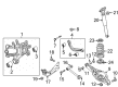
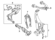
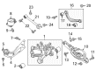
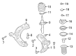
Genuine Mazda Control Arm
Suspension Arm- Select Vehicle by Model
- Select Vehicle by VIN
Select Vehicle by Model
orMake
Model
Year
Select Vehicle by VIN
For the most accurate results, select vehicle by your VIN (Vehicle Identification Number).
224 Control Arms found


Mazda Upper Control Arm Part Number: BBM2-28-C10
$104.81 MSRP: $139.78You Save: $34.97 (26%)Ships in 1-2 Business DaysProduct Specifications- Other Name: Arm, Upper-Rear
- Position: Upper
- Replaces: BP4K-28-C10B


Mazda Lower Control Arm Part Number: KD35-34-350S
$224.83 MSRP: $299.82You Save: $74.99 (26%)Ships in 1-2 Business DaysProduct Specifications- Other Name: Arm(Left), Lower
- Position: Driver Side
- Replaced by: KD35-34-350T


Mazda Lower Control Arm Part Number: B60S-34-300G
$239.45 MSRP: $319.34You Save: $79.89 (26%)Ships in 1-2 Business DaysProduct Specifications- Other Name: Arm Right, Lower
- Position: Passenger Side
- Replaced by: B60S-34-300H
- Replaces: B60S-34-300F, B45A-34-300C, B45A-34-300D, B45A-34-300E, B60S-34-300, B60S-34-300B, B60S-34-300C, B60S-34-300E, BHN9-34-300, BJV5-34-300, BJS8-34-300, BPN7-34-300C, BPN7-34-300A, BPN7-34-300B, BJS7-34-300B, B60S-34-300D, BJS7-34-300, BPN7-34-300, B60S-34-300A, BJS7-34-300A, BPN7-34-300D


Mazda Upper Control Arm Part Number: NA01-28-2A0C
$255.80 MSRP: $341.14You Save: $85.34 (26%)Ships in 1-2 Business DaysProduct Specifications- Other Name: Arm, Upper-Rear; Coil Spring, Spring Insulator, Stabilizer Bar
- Position: Upper
- Replaced by: NC10-28-C10


Mazda Lower Control Arm Part Number: GHP9-34-300M
$265.53 MSRP: $354.10You Save: $88.57 (26%)Ships in 1-2 Business DaysProduct Specifications- Other Name: Arm(Right), Lower
- Position: Passenger Side
- Replaced by: GHP9-34-300N


Mazda Upper Control Arm Part Number: N243-34-200
$367.79 MSRP: $490.48You Save: $122.69 (26%)Ships in 1-2 Business DaysProduct Specifications- Other Name: Arm(Right), Upper
- Position: Passenger Side


Mazda Lower Control Arm Part Number: N243-34-300C
$372.19 MSRP: $500.35You Save: $128.16 (26%)Ships in 1-2 Business DaysProduct Specifications- Other Name: Arm(Right), Lower
- Position: Passenger Side


Mazda Lower Control Arm Part Number: KD35-28-300
$98.61 MSRP: $131.50You Save: $32.89 (26%)Ships in 1-2 Business DaysProduct Specifications- Other Name: Arm(Right), Lower-Rear
- Position: Passenger Side
- Replaced by: KD35-28-300A


Mazda Lower Control Arm Part Number: BBM2-34-300A
$195.71 MSRP: $261.00You Save: $65.29 (26%)Ships in 1-2 Business DaysProduct Specifications- Other Name: Arm(Right), Lower
- Position: Passenger Side
- Replaces: BBM2-34-300


Mazda Lower Control Arm Part Number: GHP9-34-350M
$265.53 MSRP: $354.10You Save: $88.57 (26%)Ships in 1-2 Business DaysProduct Specifications- Other Name: Arm(Left), Lower
- Position: Driver Side
- Replaced by: GHP9-34-350N
- Replaces: GHP9-34-350A, GHP9-34-350, GHP9-34-350B, GHP9-34-350E, GHP9-34-350C, GHP9-34-350J

Mazda Upper Control Arm Part Number: B45C-28-C10
$67.56 MSRP: $90.10You Save: $22.54 (26%)Ships in 1-2 Business DaysProduct Specifications- Other Name: Arm, Upper-Rear
- Position: Upper
- Replaces: BJS7-28-C10, BJS7-28-C10B
Mazda Lower Control Arm Part Number: KA0G-34-350G
$276.64 MSRP: $368.93You Save: $92.29 (26%)Ships in 1-2 Business DaysProduct Specifications- Other Name: Arm(Left), Lower
- Position: Driver Side
- Replaced by: KA0G-34-350K

Mazda Arm Left, Upper Part Number: KJK3-34-250E
$226.44 MSRP: $301.98You Save: $75.54 (26%)Ships in 1-2 Business DaysProduct Specifications- Other Name: ARM LT, UPPER; Upper Control Arm
- Position: Driver Side
- Replaces: KJK3-34-250C, KJK3-34-250, KJK3-34-250D, KJK3-34-250A

Mazda Lower Control Arm Part Number: GHP9-28-350A
$116.45 MSRP: $155.30You Save: $38.85 (26%)Ships in 1-2 Business DaysProduct Specifications- Other Name: Arm(Left), Lower-Rear
- Position: Driver Side
- Replaces: GHP9-28-350
Mazda Lower Control Arm Part Number: B60S-34-350G
$239.45 MSRP: $319.34You Save: $79.89 (26%)Ships in 1-2 Business DaysProduct Specifications- Other Name: Arm(Left), Lower
- Position: Driver Side
- Replaced by: B60S-34-350H
- Replaces: B60S-34-350E, B60S-34-350D, BJS7-34-350, BJS8-34-350, BPN7-34-350A, BJS7-34-350A, BPN7-34-350D, BPN7-34-350B, B60S-34-350F, BJV5-34-350, BPN7-34-350, BPN7-34-350C, BJS7-34-350B
Mazda Lower Control Arm Part Number: KD35-34-300P
$208.33 MSRP: $277.82You Save: $69.49 (26%)Ships in 1-2 Business DaysProduct Specifications- Other Name: Arm(Right), Lower
- Position: Passenger Side
- Replaced by: KD35-34-300T

Mazda Lower Control Arm Part Number: DGH9-34-350A
$146.38 MSRP: $195.21You Save: $48.83 (26%)Ships in 1-2 Business DaysProduct Specifications- Other Name: Arm(Left), Lower
- Position: Driver Side
- Replaces: DGH9-34-350

Mazda Lower Control Arm Part Number: N066-34-310
$225.88 MSRP: $301.23You Save: $75.35 (26%)Ships in 1-2 Business DaysProduct Specifications- Other Name: ARM,RIGHT LOWER (BARE)
- Position: Passenger Side
- Replaces: NC10-34-310C

Mazda Upper Control Arm Part Number: KB7W-28-C10
$105.01 MSRP: $140.05You Save: $35.04 (26%)Ships in 1-2 Business DaysProduct Specifications- Other Name: Arm, Upper-Rear
- Position: Upper
- Replaces: KD35-28-C10
Mazda Lower Control Arm Part Number: BBM2-34-350A
$195.71 MSRP: $261.00You Save: $65.29 (26%)Ships in 1-2 Business DaysProduct Specifications- Other Name: Arm(Left), Lower
- Position: Driver Side
- Replaces: BBM2-34-350
| Page 1 of 12 |Next >
1-20 of 224 Results
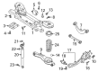
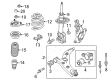
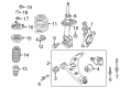
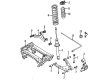
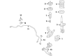
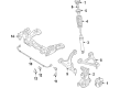
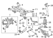
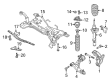
Mazda Control Arm
Mazda Control Arm prevents suspension from being thrown off by connecting the wheel to the chassis and ensuring a smooth vertical motion over bumps while maintaining tire position for confident steering. Mazda won the world's respect since 1931, combining feisty driving with ingenious engineering. Its Mazda rotary heritage displayed some bold ideas, later developed into Skyactiv engines that sip fuel but provide lively acceleration. The Kodo Soul of Motion design envelopes every surface in flowing lines that suggest movement even when standing still, and i-Activsense technology brings with it radar cruise, lane keeping and other smart aids that look out for young and seasoned drivers alike. Whether testing i-Activ AWD on gravel or introducing mild hybrids for cleaner cities, Mazda always balances efficiency, safety and fun so everyday trips are engaging. For that promise to make it to the road, the Control Arm plays an important backstage role. Acting like a hinge, it pivots on durable bushings at the subframe and holds the steering knuckle in a stout ball joint, allowing the wheel to rise over potholes while remaining pointed in the right direction. Early stamped steel versions kept prices low, but modern cast iron and lightweight aluminum versions provide added strength and reduce unsprung mass that sharpens ride quality and fuel economy across the lineup. Because of its constant geometry, the Control Arm reduces tire wear and is less susceptible to deformation from curb strikes and helps maintain the crisp steering feel for which every Mazda is known.
You'll get great performance and real durability when you pick genuine OEM Control Arm. Mazda builds these using high-quality materials and official factory methods to ensure they hold up mile after mile. You deserve that Mazda reliability without the headache of cheap knockoffs. It is easy to find exactly what you need in our huge inventory of genuine parts. Plus, every OEM part carries a real manufacturer's warranty for your peace of mind. You will love our low prices too. Order today and we will ship your brand-new parts fast. They often reach your door in just a few days.
Mazda Control Arm Parts and Q&A
- Q: How to properly remove and install a rear control arm and trailing arm on Mazda 3?A:Unscrew the lug nuts of the wheels, raise the back of the vehicle, and stabilize it with jack stands ensuring that the front wheels will not fall over and then loosen the wheel. Prop the rear lower control arm using a floor jack, loosen the lower shock absorber mounting bolt, lower the floor jack a few inches, disconnect the brake hose of the bracket, and take the arm out of the car. To install, undo the steps to the reverse and use the specified number of fasteners to tighten them to the required torque after lifting the suspension to an approximate normal ride height with a floor jack, with the level of the mark labeled IN on the upper arm facing the interior of the vehicle. Take the rear coil spring and arm out of the car but ensure that you loosen the EVAP canister mounting bolts to free the inner arm mounting bolt/nut. Installation: When installing the cam adjuster bolt, match marks must be aligned, a new nut should be used and the fasteners corroded to the recommended torque once the raising of the suspension is complete. Flooring jack on the rear lower control arm, take out lower shock absorber mounting bolt and arm. To install it, follow the reversed procedure and tighten the fasteners to the required torque with raising the suspension, so that the rib section of the arm is positioned towards the front of the vehicle. When installing a new trailing arm, detach the caliper dust shield and the four screws on the inboard side of the trailing arm then detach the wheel spindle, or in case you are reusing the same arm, leave the spindle attached. Disassemble the brake hose and brake line fittings of the trailing arm, the parking brake cable fittings of the caliper and trailing arm, and the rear auto leveling sensor lower side (where present). The lower control arm should be supported on a floor jack under the coil spring pocket, the lower shock absorber bolt removed and the trailing arm pivot bushing should be inspected to determine whether it is worn or not and it should be taken to an automotive machine shop and replaced accordingly. To install, undo the procedure the reverse, with new fasteners, lock all fasteners to appropriate torque requirements by lifting the suspension and verifying and tightening the rear wheel alignment where necessary.
- Q: What precautions should be taken when using a Control Arm during suspension bolt replacement and lower arm removal on Mazda 6?A:Warning All the suspension bolts must be changed with new ones when assembling. To remove the lower arms of 2008 and earlier model first loosen the lug nuts of the wheel on the side to be removed, raise the front side of the car, place on jackstands and take off the wheel. Detach the steering shaft and steering gear, not to rotate the steering wheel that would damage airbag clockspring. Unhook the tie-rod ends to the steering knuckles, then loosen screws of steering gear. Dis-attach the exhaust pipe(s) of the exhaust manifold(s) and place floor jack at the back of the subframe. Unscrew the front subframe mounting bolts, un screw the rear subframe mounting bolts and jack the rear of the subframe down using the jack. In either lower arm, loosen the lower arm-to-balljoint nut, and place a block of wood beneath the outer CV joint of the driveaxle to avoid harm, and a balljoint removal tool to separate the balljoint. When removing the front lower arm, also remove the damage fork mounting bolt in the front lower control arm, the arm-to-subframe mounting bolt, and then the lower control arm. To work on the 3.7L V6 models, on the right hand, in 2009 and beyond, one will have to remove the front exhaust pipe. Disassemble the ABS sensor and bracket, brake hose, the stabilizer control link upper nut, the control arm-to-knuckle nuts and lower arm-to-subframe through bolt nut. Take out the subframe support bracket mounting nut and bolts, and support the subframe on a jack, loosen the subframe mounting bolts, and then bring the subframe down to reach the bolts at the rear of the arm, and make sure to remove any mounting brackets of hoses attached to the subframe. Disassemble the subframe of the vehicle by taking out the lower arm rear mounting bolts, front through bolt and remove the arm. The top end of the steering knuckle is connected to the upper control arm by a balljoint and to two spots on the chassis by the pivot bolts. Unscrew the wheel speed sensor and 3 upper strut-to-body nuts, detach the balljoint on top of the steering knuckle, and unscrew the inner arm mounting bolts and the upper arm. In the case of 2009 and subsequent models, disassemble the transverse member with the removal of the transverse member mounting nuts then the transverse member itself. Check distortion of the control arm and wear of bushings, replacing where needed, and never make the attempt to straighten a bent control arm. Installation is the opposite of removal, which is to make sure that all the fasteners are tightened up to required torque values. Positively lift the outer end of the control arm using a floor jack before securing the fasteners of the control arm to create simulated normal ride height. In the case of upper control arms, the pivot bolts are to be installed loosely and a 0.25-inch diameter drill bit through the two holes that are cut just below the bushing is used to position the appropriate height setting of the pivot bolts. Lastly, attach the wheel and lug nuts and then lower the vehicle and screw-in the lug nuts until they reach the required torque and after finishing the job it is always recommended to check front wheel alignment and adjust the lug nuts as needed.


Related Mazda Parts
 Mazda Coil Springs
 Mazda Wheel Bearing
 Mazda Wheel Cover
 Mazda Axle Beam Mount
 Mazda Control Arm Nut
 Mazda Crossmember Bushing
 Mazda Leaf Spring Bushing
 Mazda Leaf Spring Shackle
 Mazda Steering Knuckle Bushing
 Mazda Suspension Strut Rod
 Mazda Sway Bar Link Bushing
 Mazda Torsion Bar
Browse by Model
2 Control Arm 3 Control Arm 323 Control Arm 5 Control Arm 6 Control Arm 626 Control Arm 929 Control Arm B2000 Control Arm B2200 Control Arm B2300 Control Arm B2500 Control Arm B2600 Control Arm B3000 Control Arm B4000 Control Arm CX-3 Control Arm CX-30 Control Arm CX-5 Control Arm CX-50 Control Arm CX-7 Control Arm CX-70 Control Arm CX-9 Control Arm CX-90 Control Arm Miata Control Arm Millenia Control Arm MPV Control Arm MX-3 Control Arm MX-30 EV Control Arm MX-5 Miata Control Arm MX-6 Control Arm Protege Control Arm Protege5 Control Arm RX-7 Control Arm RX-8 Control Arm Tribute Control Arm