×
- Hello
- Login or Register
- Quick Links
- Live Chat
- Track Order
- Parts Availability
- RMA
- Help Center
- Contact Us
- Shop for
- Mazda Parts

My Garage
My Account
Cart
Genuine Mazda Tribute Rack And Pinion
Steering Gear- Select Vehicle by Model
- Select Vehicle by VIN
Select Vehicle by Model
orMake
Model
Year
Select Vehicle by VIN
For the most accurate results, select vehicle by your VIN (Vehicle Identification Number).
4 Rack And Pinions found
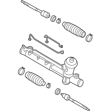
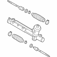
Mazda Tribute Steering Gear Part Number: ZZDM-32-110R-0A
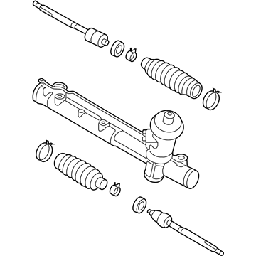
Mazda Tribute Steering Gear Part Number: ZZCA-32-110
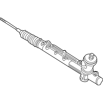
Mazda Tribute Steering Gear Part Number: EC03-32-110R-0A
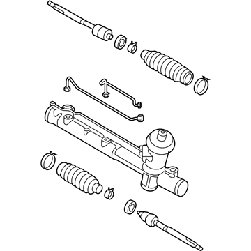
Mazda Tribute Steering Gear Part Number: EC01-32-110R-0A
Mazda Tribute Rack And Pinion
Looking for Rack And Pinion with proven quality? Choose OEM Rack And Pinion. Mazda designs and builds them to strict factory specs. Every piece goes through rigorous quality checks. You'll get parts that fit right and work like new. Shop our huge inventory of OEM Mazda Tribute parts. Enjoy the highly competitive prices online. Our site is your one-stop shop. Each genuine Tribute part includes a manufacturer's warranty. Buy with confidence. Our return policy is simple and hassle-free. In a rush? Choose expedited delivery at checkout. You'll love the streamlined experience from search to checkout to receiving your order.
Mazda Tribute Rack And Pinion Parts and Q&A
- Q:How do Rack And Pinion play a role in removing and installing steering gear on Mazda Tribute?A:In 2007 and older models, first remove the cable out of the negative terminal of the battery, and then the rear transaxle mount and bracket. Disconnect the power steering pressure and return line bracket bolts and inside the car, slide the steering shaft boot up through the firewall and remove and dispose the intermediate shaft pinch bolt and nut. Depower the resistant fluid on the remote reservoir either with a suction gun or by detaching the fluid hose. Unscrew the front wheel lug nuts, lift the front part of the vehicle using jackstands then remove both front wheels. It is necessary to separate the tie-rod ends of the Steering Knuckles, label the U-joint and Rack And Pinion input shaft, and part the U-joint and Rack And Pinion input shaft. Install a drain pan beneath the Rack And Pinion by disconnection of the pressure and return lines of the power steering and capping the ends to avoid the loss of fluid. Unbolster the Rack And Pinion by removing the two mounting bolts and take the Rack And Pinion out of the vehicle. To install, undo all the steps made, making certain that when attaching the Rack And Pinion input shaft to the intermediate shaft U-joint, matchmarks are aligned and a new pinch bolt and nut are installed. Fasten all the fasteners to the recommended torque levels, re-connect the battery and give the Powertrain Control Module time to re-learn its idle and fuel mixture trim strategy. Refill the power steering tank with the suggested fluid, bleed the hydraulic system and verify the front end alignment. For 2008 and later models, remove the battery cable, loosen lug nuts on the front wheel and lift the vehicle on jackstands and remove the front wheels. Unscrew the Rack And Pinion on the steering shaft, loosen the two bolts that hold the Rack And Pinion in place, and take out the steering gear shield, where fitted. Disassemble tie-rods and steering knuckles, take out the through-bolt in rear transaxle mount in 4WD models and transmission vibration damper in four-cylinder models with automatic transaxle. Undo the Rack And Pinion mounting bolts which might need a bit of lowering of the rear of the front subframe and remove the Rack And Pinion through the left side of the vehicle drawing the driveshaft downward in 4WD models. During installation, position the Rack And Pinion in the middle of the travel before installing, screw all the fasteners to the recommended torque values and finally check the front end alignment. In models as of 2013 and later, disassemble by removing the subframe and Rack And Pinion input shaft boot, the Rack And Pinion bolts and then swivel the stabilizer bar upwards to disconnect the Rack And Pinion from the subframe. Installation To install, follow the removal procedure, attach the Rack And Pinion mounting bolts in order to the outlined torque and reassemble the subframe.
Related Mazda Tribute Parts
 Mazda Tribute Power Steering Hose
 Mazda Tribute Power Steering Pump
 Mazda Tribute Power Steering Reservoir
 Mazda Tribute Ignition Lock Assembly
 Mazda Tribute Power Steering Pump Pulley
 Mazda Tribute Rack and Pinion Boot
 Mazda Tribute Steering Column
 Mazda Tribute Steering Shaft
 Mazda Tribute Steering Wheel
 Mazda Tribute Tie Rod
 Mazda Tribute Tie Rod End